GEOMETRY DESCRIPTION
Illumination Geometry
The relative Sun position regarding to the Earth surface is completely determined by the illumination geometry. In this case, the angles involved are zenith solar angle (q0) and the azimuth solar angle (f0).
The zenith solar angle represents the Sun position relative to the local normal. It has values between 0º and 90º, and is calculated by the following equation:
![]()
where j, d and h are the latitude, the solar declination and the time angle respectively.
The azimuth solar angle f0 is determined Sun position projection over the Earth surface. It varies from 0º a 360º and is calculated by the following equations:
The minus sign in these expressions corresponds to the South Hemisphere Convention for angles measurements. In the North Hemisphere the azimuth angle is measured from South to East, therefore these equations have a plus sign instead of a minus sign.
Figure 1 shows different geometric configurations. Figure 1(a) represents the spherical geometry for a westerner pixel, whose observation point Pw is fixed to the surface. Figures 1(b) and 1(c) represents the azimuth observation planes for a westerner and eastern pixel respectively according to operation mode Mas and Mds (ascending and descending). The first one is the real case of an illuminated scene by the afternoon Sun and the second is the real case of an illuminated scene by the morning Sun. It´s implicit the dependence of the angles with the pixel position. NOTE: the zero subscript for some variables is an indication that they are considered in the illumination direction.
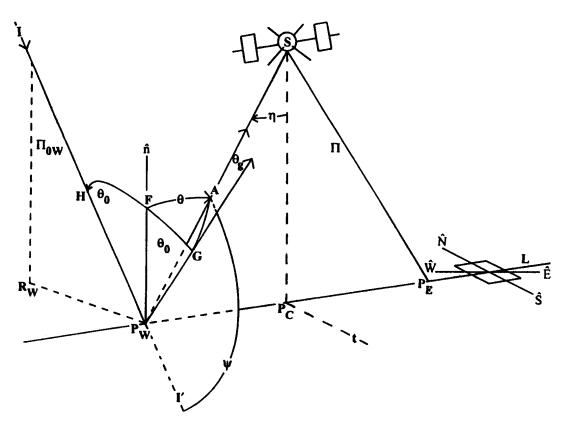
Figure 1 (a): Spherical geometry for a westerner pixel.
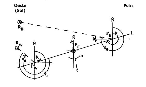
Figure 1 (b): Azimuth observation plane for a westerner pixel.
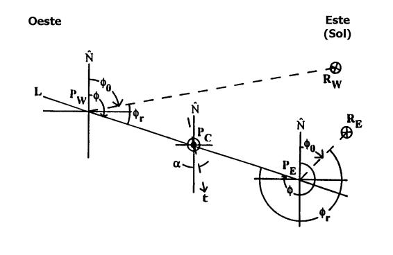
Figure 1 (c): Azimuth observation plane for an eastern pixel.
Observation Geometry
The relative sensor position with respect to the Earth surface is completely determined by the observation geometry. The angles involved in this case are the zenith sensor angle and the azimuth sensor angle.
The sensor zenith angle q represents the satellite position relative to the normal and is given by the following formula:
![]()
where h [km] is the sensor altitude, RT [km] is the terrestrial radius and h is the sweep angle. The (1+ h/RT) factor takes in account the Earth curvature, supposing, for simplicity, a circular sensor orbit.
The azimuth sensor angle f is determined by the sensor position projection over the Earth surface, according to the following equations:
where jS and lS are the sub-satellite point latitude and longitude, jP and lp are the observed pixel latitude and longitude over the sweep line.
Observation and Illumination Geometry
Combination
Combining illumination and observation geometries other important angles for remote sensing are obtained, by example, scattering angle Y and glint angle qg .
The scattering angle Y is defined between the incident direction and the observation direction, it varies from 0º to 180º and is given by the following formula:
![]()
where m =cos(q ) and fr is the relative azimuth angle, defined by the sensor position with respect to the Sun position, both projected to the Earth surface.
The glint angle qg is defined by:
![]()
![]()